Lag screw technique
1. Principles
The primary function of a lag screw is to compress one piece of bone against another. This technique is commonly used to achieve absolute stability, which promotes direct bone healing, as opposed to healing with callus formation.
Screw design
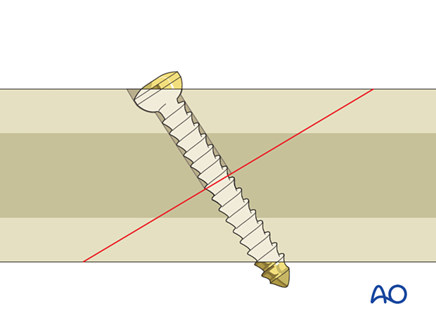
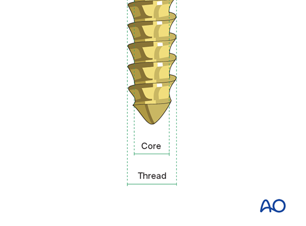
A screw has a specific core diameter and a thread diameter (which is the screw diameter).
With gliding hole - compression
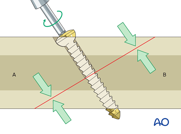
As the screw is tightened, the compressive effect occurs between the undersurface of the screw head on segment A and the threads at the far end of the screw in segment B.
To achieve this the screw must be able to glide in the near hole (gliding hole) without the threads obtaining purchase, so a screw-diameter hole must be drilled in segment A.
For the screw threads to obtain purchase in the far cortex, a pilot hole of the core diameter must be drilled in segment B.
This 3D model shows cortical lag screw fixation.
Contraindications for lag screws
Interactive 3D animationThe lag screw technique compresses fracture fragments together, making it contraindicated in comminuted fractures.
This 3D model shows cortical lag screw fixation of a comminuted fracture. Under specific circumstances, a lag screw can be used to compress large fracture fragments (the red fragments) of a multifragmentary fracture in order to secure added stability. However, a single lag screw is not capable of stabilizing all fracture fragments and should therefore be augmented with other implants (eg, a plate) to create a stable fixation.
Without gliding hole – no compression
If the near cortex is not over drilled, the screw threads will engage in both the near and far cortices, preventing compression.
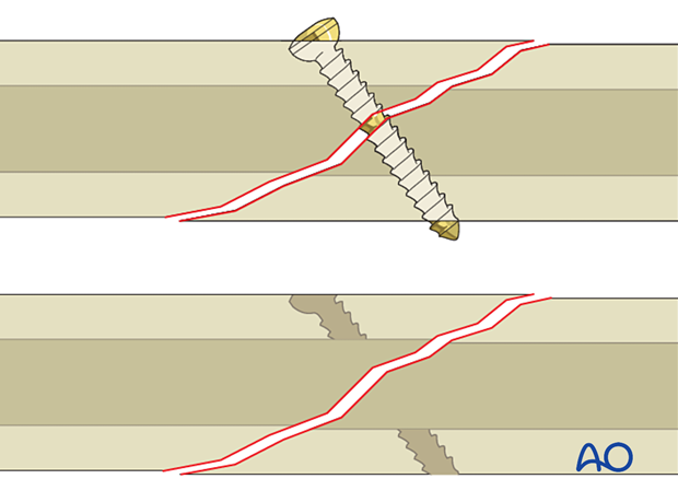
These 3D models show the effect of drilling a thread-diameter hole in the near cortex. To achieve fracture gap compression (top animation), it is essential to drill a screw-diameter hole in the near cortex. If this is not done, the screw threads will engage both cortices which prevents the compression of the fracture fragments (bottom panel).
Screw direction
The axis of the screw should be as perpendicular as possible to the plane of the fracture.
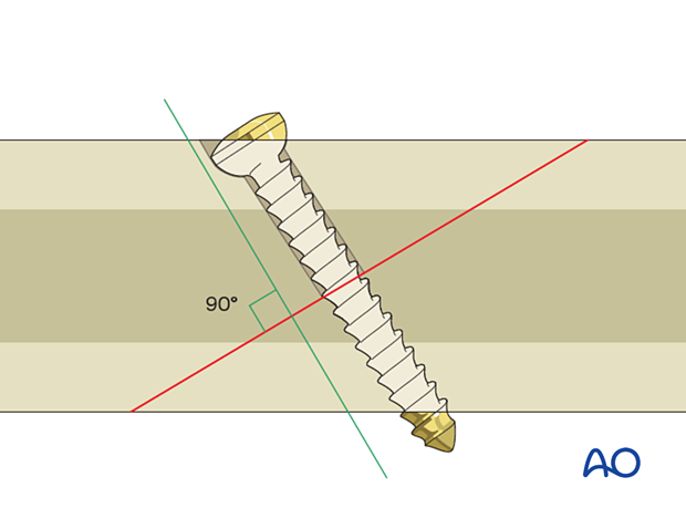
If the screw is far from perpendicular, there will be a shearing force as it is tightened which risks displacing the fracture.
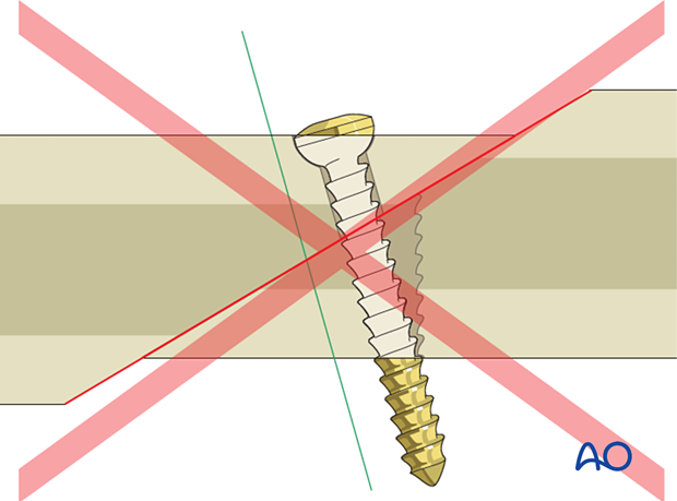
These 3D models show the biomechanical behavior of the construct. In the top animation, the lag screw is correctly positioned perpendicular to the fracture plane. In the bottom panel, the screw is not perpendicular to the fracture plane, and as it is tightened there will be a tendency for the fragments to displace.
2. Screw insertion technique
How to start drilling
When drilling obliquely to the bone surface, the drill’s point can easily slide along the bone. It is helpful to first orient the drill perpendicular to the near cortex to start the hole before gradually reorienting it perpendicular to the fracture plane.
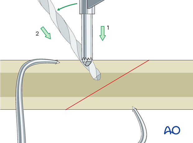
Gliding hole
Drill the gliding hole in the near cortex using a drill bit with the same diameter as the thread diameter of the screw.
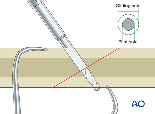
To ensure the pilot hole has the same axis as the gliding hole, insert a drill sleeve with the gliding hole's outer diameter and the inner diameter of the intended pilot hole. For the threads to engage in the pilot hole, the distal hole's diameter must correspond to the core diameter of the screw.
Drill the pilot hole, ensuring the drill bit penetrates the far cortex.
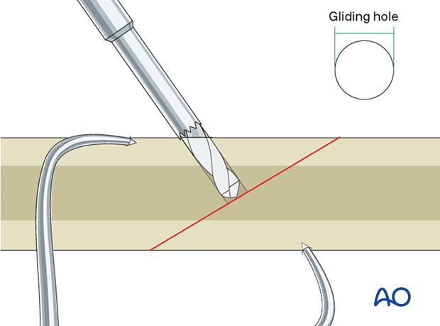
To ensure that the pilot hole has the same axis as the gliding hole, insert a drill sleeve with the gliding hole's outer diameter and the inner diameter of the intended pilot hole (centering device). For the threads to engage in the pilot hole, the distal hole's diameter must correspond to the core diameter of the screw.
Drill the pilot hole. The drill bit should penetrate the far cortex.
Countersinking
The gliding hole should be countersunk to increase the contact area of the under-surface of the screw head and reduce stress on the near cortex.
Countersinking also makes the screw head less prominent, which may be desirable in areas with thin soft-tissue coverage.
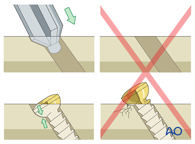
These 3D models show the effect of countersinking. In the top animation the countersinking is properly executed, allowing a homogenous force distribution on the bone. The bottom animation shows insufficient countersinking, causing an eccentric and concentrated loading on the bone, which decreases the degree of compression and might lead to bone resorption due to the high stresses.
To avoid this, countersinking should be performed manually, and not with a power tool.
If too much bone is removed during countersinking, a single-hole plate may be used as a washer.
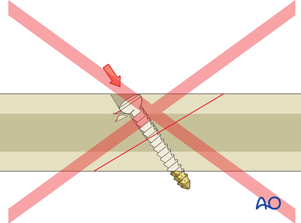
These 3D models show the effect of excessive countersinking. In the top animation the countersinking is performed correctly. In the bottom animation, there is excessive countersinking and the bone stock of the near cortex below the screw head (shown in red) might become too weak to sustain the screw force required to compress the bone fragments, causing sinking and potential failure.
Determine screw length
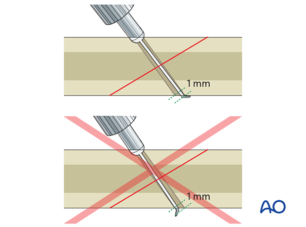
Measure the depth of the hole.
It is better for the hook on the depth gauge to catch on the longer side of the drill hole, as shown.
Alternatively, if it is not possible to engage the hook, measure the shorter side of the drill hole, but this may underestimate the required screw length. The surgeon must make an allowance for this.
The screw's tip should protrude 1–2 mm through the opposite cortex to ensure full thread purchase.
Screw insertion
As the near hole is a gliding hole, the screw threads will not engage allowing the screw to glide freely.
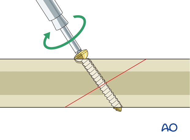
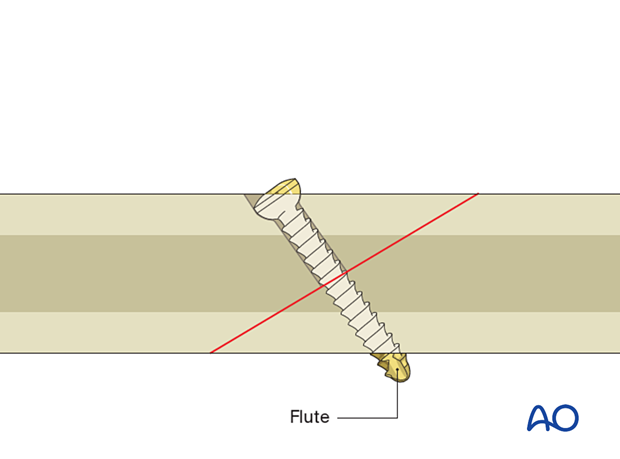
When using a self-tapping screw, the flute should lie outside of the screw hole when the screw is tightened, requiring a slightly longer screw.
However, a screw that is too long may cause soft-tissue irritation.
